... from an idea to superior design performance with mathematical modelling and engineering analysis ...
Flow in non-uniform magnetic field
Introduction
Magneto-Hydro-Dynamics (MHD) effects associated with a non-uniform
magnetic field have the capacity to significantly modify the fluid
velocity profile and to induce flow instabilities that affect mass
and heat transfer as well as corrosion rates. The reported 3D nature
of the flow arises from the spatial variation of the applied transverse
magnetic field.
Modelling of such flow conditions is necessary to predict performance
of liquid metal systems that are subjected to magnetic fields in fusion reactors.
Experimental measurements underpinning this validation effort were
performed in ALEX facility at Argonne National Laboratory [1].
Objectives
The selected test case is well-documented in open literature [1, 2, 3 & 4].
The flow conditions are very sensitive to the selected combination of boundary conditions.
Due to flow instability in the area of rapidly decreasing magnetic field, and
the downstream laminar-to-turbulent flow regime transition, transient CFD simulations
are required.
Two CFD simuulations were conducted to validate the simulation results against
the experimental data and to test sensitivity of the simulation process
when using tetrahedral or hexahedral grid elements.
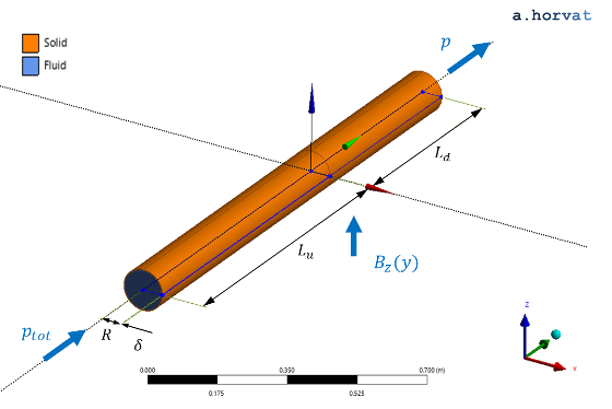
Geometry
Pipe inner radius (R) is 0.0541 m.
Wall thickness (`delta`) is 0.0026 m.
Upstream length (Lu) is 0.541 m.
Downstream length (Ld) is 0.8115 m.
Loading
The fluid motion is induced by prescribing a pressure difference (19.5 kPa)
in the streamwise (y) direction that yields the flow speed of approximately 0.07 m/s [2].
The volumetric Lorentz force that transforms and laminarise the flow field is the result of a non-uniform,
transverse magnetic field:
`B_x = 0.0` `"T"`, `B_y = 0.0` `"T"`, `B_z = 0.5 B_0(1-tanh(0.45(y//R - 0.4)))`
where `B_0 = 2.135` `"T"`.
Material properties
The material properties of NaK eutectic [1 & 4] are used for the simulated cases:
`rho` is density of 865.4 kg/m3;
`mu` is dynamic viscosity of 9.118·10-4 Pa s;
`sigma` is electrical conductivity of 2.88·106 S/m.
For the conjugate cases, material properties of 316 stainless steel [4]
are selected for the solid layers:
`sigma_s` is electrical conductivity of 1.618·106 S/m,
which yields the wall conductance `c = sigma_s delta//sigma R` of 0.027.
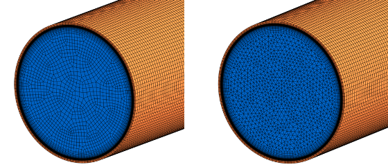
Meshing
An influence of two different types of grid elements is investigated. The first
simulation is performed using the grid with tetrahedral elements, and the second
with the hexahedral elements.
Numerical grid with hexahdral elements (left) and tetrahedral elements (right)
In both cases, the numerical grid is extruded for the solid pipe:
A uniform spacing of 3.0 mm is applied in the streamwise (y) direction.
In the tangential direction, 128 elements are used to discretise the pipe's
wall circumference.
Across the pipe wall thickness, 19 elements are employed with an initial radial spacing of 0.6 µm
near the fluid-solid interface and with a growth
rate of 1.5.
For the fluid domain:
A uniform element size of 3.0 mm is prescribed to the flow cross-sectional
area (hexahedral grid) or to the domain volume (tetrahedral grid).
The numerical grid is refined near the fluid-solid interface by 42 layers of
hexahedral elements. Their first layer thickness is 0.6 µm and the growth rate 1.2.
The utilised hexahedral numerical grid contains 4.06 mil nodes and 4.02 mil elements.
For the tetrahedral numerical grid, the number of grid nodes and elements slightly
increases to 4.07 mil and 6.52 mil, respectively.
Initial conditions
The initial conditions in the simulation domain are equal to the reference
conditions (`p_(ref)`), zero flow speed and zero electric potential.
Boundary conditions
At the inlet, the total pressure (`p_(t o t) = p_(ref) + 19.5` `"kPa"` ) is
prescribed to allow for the flow field to freely develop. The level of
reference pressure (`p_(ref)`) is unimportant due to incompressibility
of the fluid.
For the outlet boundary, the fixed pressure condition (`p = p_(ref)`)
is appropriate.
The no-slip condition (`u = 0.0` `"m"//"s"`) is assigned
to the fluid-solid interface. The currect density (`j`) is also preserved across
the interface in the normal direction.
The zero electric potential (`phi = 0.0` `"V"`) is set to the pipe's
surface near the outlet to minimise any flow disturbance due to induced electrical currents.
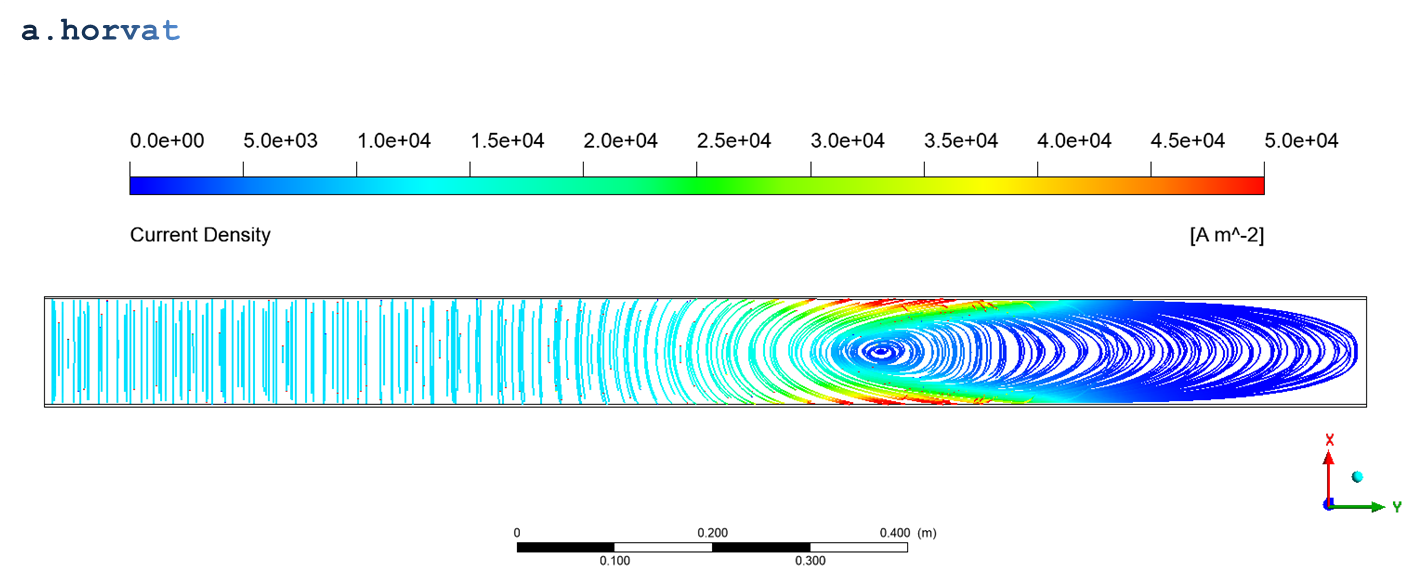
Results
An upstream part of the circular duct is subjected to transverse magnetic field
where the volumetric Lorentz force transforms and laminarise the flow field.
The induced electic current density is shown below.
Electric current density (`j`)
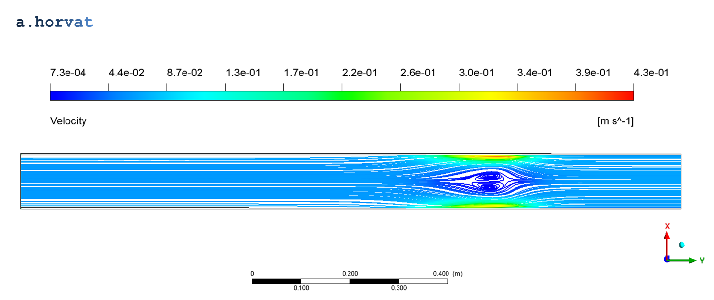
With reduction of the external magnetic field, the flow regime becomes unsteady
and eventually turbulent. The nagative pressure gradient decreases significantly
and may locally even change the sign resulting in flow recirculation.
Flow velocity (`v`) with the recirculation area
Streamwise variation of pressure is recorded along the pipe centreline, and
the wall proximity: `x_(max) = 0.0540` `"m"` and `z_(max) = 0.0540` `"m"`.
For comparison with the experimental data [2 & 4], the non-dimensionalised
streamwise pressure gradient (`-dp//dy`) and the spanwise pressure difference (`dp = p_(x max) - p_(z max)`)
are used. Hexahedral numerical grid
The imposed pressure difference induces the mass flow rate `dot m = 0.5486` `"kg"//"s"`,
which results in
average flow speed `u = dot m//rho pi R^2 = 0.06870` `"m"//"s"`,
Reynolds number `Re = rho u R//mu = 3540`,
Hartmann number `Ha = B_0 R sqrt( sigma//mu ) = 6491`,
interaction parameter `N = Ha^2//Re = 11904`.
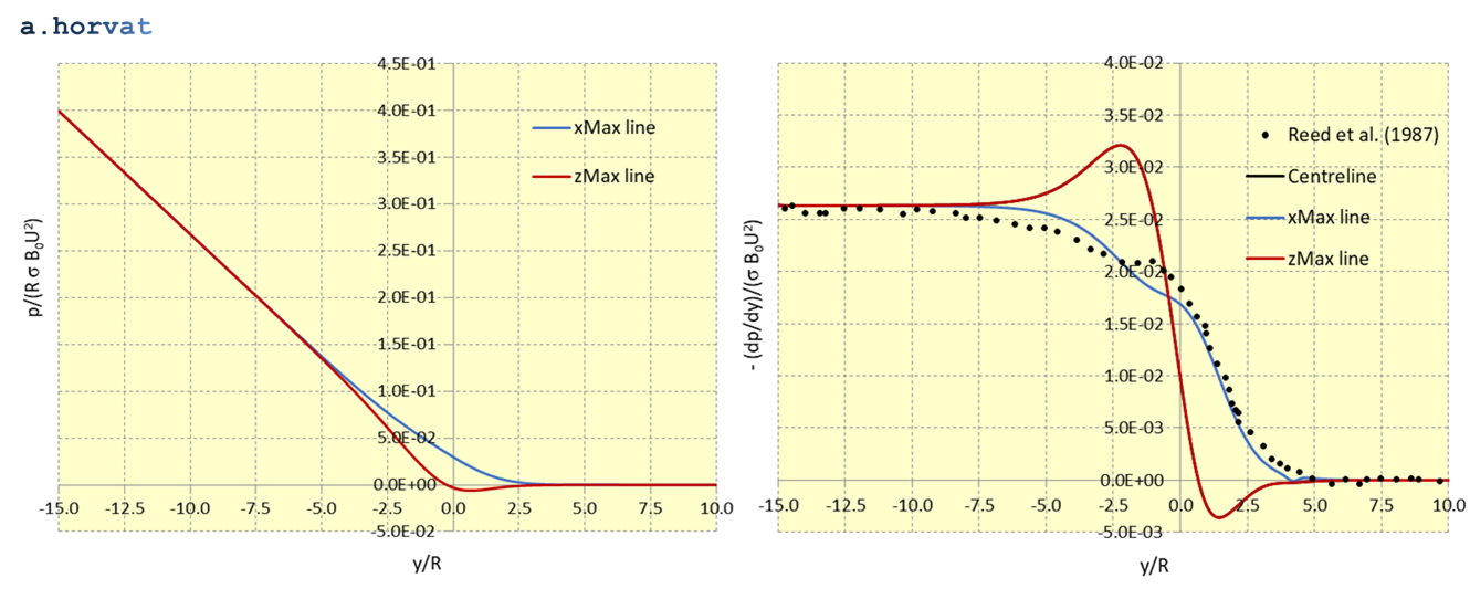
Calculated streamwise variations of non-dimensionalised pressure (`p`), its gradient (`-dp//dy`)
and wall pressure difference (`dp`) are presented below for the case with the hexahedral grid.
Non-dimensionalised pressure and its gradient along the wall (hexahedral grid)
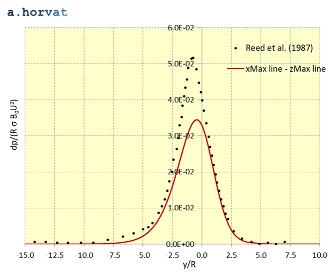
Non-dimensionalised pressure difference along the wall (hexahedral grid)
For validation purposes, quadratic mean (or RMS) of deviation between the experimental data
[2 & 4] and the CFD simulation results is calculated for the pressure gradient (`-dp//dy`)
and the wall pressure difference (`dp`):
RMS of deviation
`-(dp//dy)//(sigma B_0 u^2)`
6.959E-3
`dp//(R` `sigma B_0 u^2)`
2.873E-2
Tetrahedral numerical grid
The imposed pressure difference induces the mass flow rate `dot m = 0.5537` `"kg"//"s"`,
which results in
average flow speed `u = dot m//rho pi R^2 = 0.06934` `"m"//"s"`,
Reynolds number `Re = rho u R//mu = 3573`,
Hartmann number `Ha = B_0 R sqrt( sigma//mu ) = 6491`,
interaction parameter `N = Ha^2//Re = 11795`.
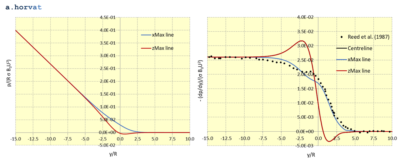
Calculated streamwise variations of non-dimensionalised pressure (`p`), its gradient (`-dp//dy`)
and wall pressure difference (`dp`) are presented below for the case with the tetrahedral grid.
Non-dimensionalised pressure and its gradient along the wall (tetrahedral grid)
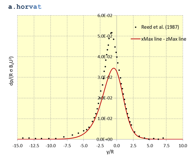
Non-dimensionalised pressure difference along the wall (tetrahedral grid)
For validation purposes, quadratic mean (or RMS) of deviation between the experimental data
[2 & 4] and the CFD simulation results is calculated for the pressure gradient (`-dp//dy`)
and the wall pressure difference (`dp`):
B.F. Picologlou and C.B. Reed, Experimental investigation of 3-D MHD flows at high Hartmann number and interaction parameters, 1988, Tech. Report DE89 003643, Argonne National Lab, IL, USA.
C.B. Reed, B.F. Picologlou, T.Q. Hua, and J.S. Walker, ALEX results: A comparison of measurements from a round and a rectangular duct with 3D code predictions, 1987, Tech. Report DE88 005947, Argonne National Lab, IL, USA.
A. Khodak, Numerical analysis of 2-D and 3-D MHD flows relevant to fusion applications, IEEE Transactions on Plasma Science, Vol. 45, Issue 9, Sept. 2017.
A. Tassone, Study on liquid metal magnetohydrodynamic flows and numerical application to a water-cooled blanket for fusion reactors, Ph.D. thesis, Sapienza - University of Rome, 2019.
Dr Andrei Horvat
M.Sc. Mechanical Eng.
Ph.D. Nuclear Eng.