... from an idea to superior design performance with mathematical modelling and engineering analysis ...
Wall boiling
Introduction
Boiling is one of most effective heat transfer mechanisms. The ability
to accurately predict such phase change phenomenon is of great importance
in process and power generation industries. Although most commonly used,
boiling in water flow represents a significant challenge due to large density
difference between both phases (i.e. liquid water and steam) and latent
heat of vaporisation.
Boiling is usually induced by a heated wall where vapour bubble creation and
their departure are governed by processes that cannot be resolved by a numerical
grid. For that reason, additional mathematical models are necessary to capture
this important heat transfer phenomenon.
Objectives
The wall boiling flow test case examines the capability of the modelling
software to predict phase change phenomena with large density changes and
especially the wall boiling. Significant buoyancy forces and heat
transfer associated with vaporisation and condensation in the surrounding,
subcooled environment may represent an additional challenge.
CFD simulations of water flow in an annulus shall be conducted for selected,
specific experimental conditions [1 & 2] where the heat flux is high enough
to produce substantial vaporisation with the local vapour volume fraction
reaching 30%.
The CFD simulation results shall be used to calculate radial distribution
of void fraction (i.e. vapour volume fraction), vapour and liquid velocities
at a specified axial location, where the experimental data was collected
[1 & 2]. Such radial profiles tend to be more selective than the flow
variable axial distributions.
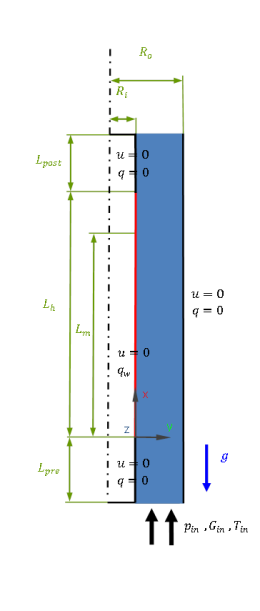
Geometry
Radius of heating element (Ri) is 9.5 mm.
Tube external radius (Ro) is 18.75 mm.
Length of the heating element (Lh) is 1.67 m.
Length of the upsteam section (Lpre) is 0.28 m.
Length of the downstream section (Lpost) is 0.30 m.
Elevation of the measuring plane (Lm) is 1.61 m.
Using axisymmetry, the simulation domain can be a two-dimensional tangential slice of the
annular geometry. Poor convergence due to restrained entrainment may force
the user to simulate a wider tangential section.
Loading
The fluid motion is induced by the prescribed water inlet mass flux `G_(i\n)`.
A constant heat flux `q_w` is assigned along the vertical inner wall of
the annulus. Two cases are analysed:
1) `G_(i\n) = 474` `"kg"//"m"^2 s`, `q_w = 152.3` `"kW"//"m"^2`
2) `G_(i\n) = 1059.2` `"kg"//"m"^2 s`, `q_w = 251.5` `"kW"//"m"^2`
Material properties
Water-vapour mixture properties based on IAPWS IF97 steam tables [3] (or equivalent) shall be
used in the modelling analysis.
They should cover the pressure range between 100 and 200 kPa, and the
temperature range between the 30°C of subcooling and the saturation
conditions.
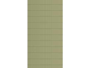
Meshing
Hexahedral grid elements are used in the both simulated cases. In the
radial direction, the grid spacing is compressed near the inner perimeter
of the annulus to 0.089 mm and then expanded in the radial direction to 0.178 mm.
Section of the numerical grid
In the axial direction, a uniform grid spacing of 4 mm is applied. Furthermore,
4 grid nodes are used in the tangential direction to discretise the 2° large annular section.
Initial conditions
Due to the steady-state nature of the boiling heat transfer case, initial
conditions are not important. They should be used to enhance stability
of the solution procedure.
Boundary conditions
At the inlet, the following mass flux values and temperatures used
in the experiments [2] shall be prescribed:
At the outlet, a fix pressure level should be set, which has to be adjusted
to meet the requested inlet subcooling conditions:
1) `p_(i\n)=0.142` `"MPa"`
2) `p_(i\n)=0.143` `"MPa"`
Due to pressure dependence of the boiling location, it may be more suitable
to impose fix pressure conditions at the inlet and mass flux at the outlet.
At the section of the inner wall occupied by the heater (Lh), the
following heat flux values and the no-slip boundary conditions shall
be prescribed:
The sections of the internal wall up- and down-stream the heater,
as well as the external wall are to be kept adiabatic with no-slip
boundary conditions.
For the vertical, tangential surfaces, symmetry or equivalent
conditions shall be used.
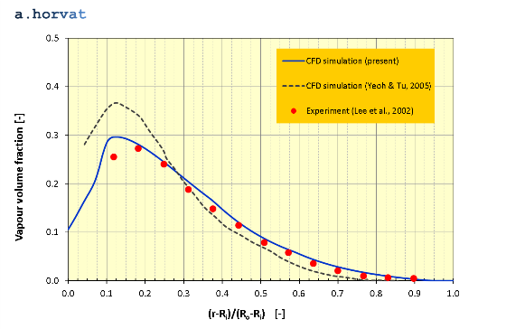
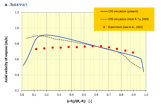
Results
The simulation results were obtained using a double precision CFD solver.
For both analysed cases, the calculated radial distribution of vapour volume fraction,
liquid and vapour velocities at the elevation Lm
are compared with published experimental and other CFD results [1 & 2]. Case 1
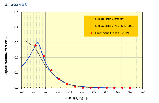
Radial distribution of vapour volume fraction at `x = L_m` for Case 1
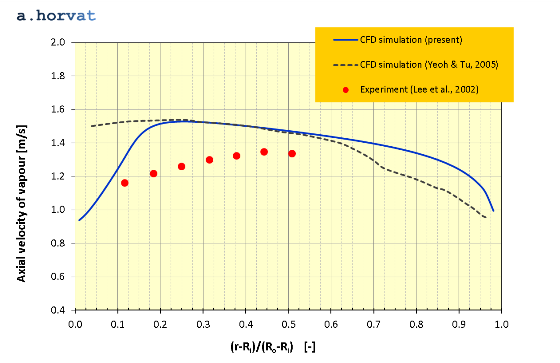
Radial distribution of vapour axial velocity at `x = L_m` for Case 1
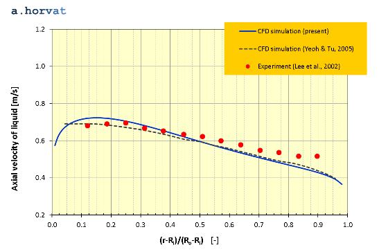
Radial distribution of liquid axial velocity at `x = L_m` for Case 1
Quadratic mean (or RMS) of deviation between the experimental data [1] and the current CFD simulation
results is calculated for Case 1:
RMS of deviation
vapour volume fraction
0.014
vapour axial velocity
0.092 m/s
liquid axial velocity
0.042 m/s
Case 2
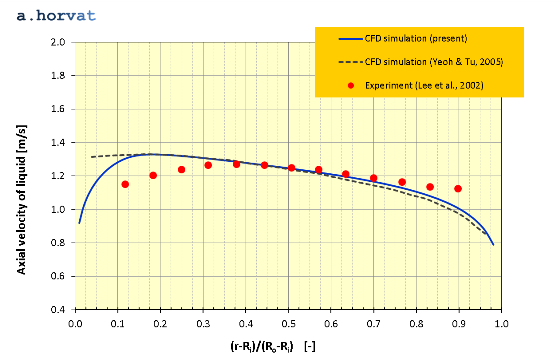
Radial distribution of vapour volume fraction at `x = L_m` for Case 2
Radial distribution of vapour axial velocity at `x = L_m` for Case 2
Radial distribution of liquid axial velocity at `x = L_m` for Case 2
Quadratic mean (or RMS) of deviation between the experimental data [1] and the current CFD simulation
results is calculated for Case 2:
T.H. Lee, G.-C. Park, D.J. Lee, Local flow characteristics of subcooled boiling flow of water in a vertical annulus, Int. J. Multiphase Flow, 2002 Vol. 28, 1351-1368.
G.H. Yeoh, J.Y. Tu, A unified model considering force balances for departing vapour bubbles and population balance in subcooled boiling flow, Nuclear Engineering and Design, 2005, Vol. 235, pp. 1251-1265.
The international association for the properties of water and steam, www.iapws.org/relguide/IF97-Rev.pdf, accessed 2016/07/14.
Dr Andrei Horvat
M.Sc. Mechanical Eng.
Ph.D. Nuclear Eng.