... from an idea to superior design performance with mathematical modelling and engineering analysis ...
Numerical grid deformation
Introduction
CFD simulations often require moving boundaries either to model the prescribed
motion of the structural elements (e.g. closure of a valve) or the response of
the body to the fluid motion (e.g. wing flatter). Where the so-called body fitted
numerical meshes and the underlying models are used, the numerical grid has to
follow such boundary motion. This requires deformation of the numerical grid
without losing the ability to discretise the fluid flow equations and to reach
a converging solution.
The quality of the numerical grid is often judged by the size and distribution
of the control volume angles. If any element angle becomes too small or even
negative, the numerical simulation will fail. Although the numerical grid deformation
may decrease the minimum size of the control volume angle, any periodic
deformations shall not lead to its permanent reduction.
Objectives
Test the grid deformation capability by examining the extent of permanent element
deformation due to periodic boundary displacements. Minimal face angle of all
control volumes in the simulation domain can be used to characterise performance
of the grid deformation algorithm.
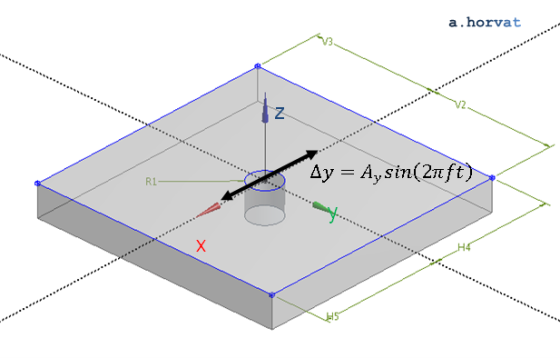
Geometry
Cylinder diameter (2 R1) is 0.2 m.
Domain length (H4+H5) and width (V2+V3) are 1.6 m.
Domain height is 0.2 m (although not important due to the case two-dimensionality).
Loading
Sinusoidal oscillations in the y-direction are forced by prescribing a displacement
function `Delta y=A_y sin(2 pi f t)` to the cylinder where:
`A_y` is displacement amplitude set to 0.2 m;
`f` is forced oscillation frequency set to 20 Hz;
`t` is time.
Note that the oscillation frequency (`f`) does not influence the grid deformation although
it determines the size of the integration timestep.
Material properties
Not applicable; the test scenario is limited to the grid deformation capability of
the CFD algorithm.
Meshing
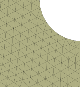
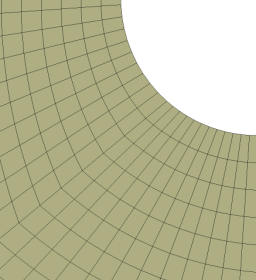
An influence of two different types of grid elements is investigated. The first simulation
is performed using the grid with tetrahedral elements, and the second with the hexahedral
elements. a)
b)
Section of numerical grid: (a) tetrahedral and (b) hexahedral elements
In both cases, the size of elements is set to 0.02 m at the cylinder wall, which is only 10% of
the imposed cylinder displacement amplitude. The element size is kept uniform in the tetrahedral
grid arrangement. On the other hand, the grid spacing expands in the hexahedral grid due
to the underlying block structure.
In the z-direction, the 2D grid elements are extruded for a single grid spacing across the
simulation domain.
Initial conditions
Zero displacement (` Delta y=0`) of the cylinder walls
Boundary conditions
Zero displacement `Delta x=0` and `Delta y=0` for the external domain boundaries at `x_min`, `x_max`, `y_min` and `y_max`
Prescribed grid displacement `Delta x=0` and `Delta y=A_y sin(2 pi f t)` for the cylinder walls
Symmetry or equivalent conditions for any motion in the z-direction
Results
The simulation results were obtained with the timestep of `1//32f` using a single precision CFD solver.
Grid node displacement due to imposed external boundary motion (tetrahedral mesh)
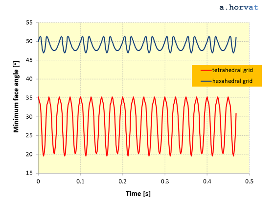
Behaviour of the minimum face angle is investigated for the tetrahedral and the hexahedral
numerical grid. The lowest minimum angle is reached as the moving cylinder reaches the maximum displacement point.
Time variation of the grid minimum face angle
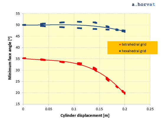
Grid node displacement versus minimum face angle
The minimum face angle in the tetrahedral grid changes between 19.6° and
35.3° during the imposed cyclic deformations. The lowest value of the
minimum face angle decreases only slightly, for 0.001% per cycle.
These size changes of the minimum angle are even smaller when the hexahedral grid is used. During the
numerical simulation the minimum face angle swings between 47.06° and
51.4°. The lowest value further decreases, but only for 0.0001% per cycle.
 a)
a)
 b)
b)