... from an idea to superior design performance with mathematical modelling and engineering analysis ...
Laminar, isothermal backward facing step
Introduction
In a flow system, where the flow cross-section expands too rapidly for the
flow to follow, flow separation and subsequent reattachment may occur.
There are numerous such examples in engineering applications e.g. a wide
angle diffuser, a sharp bend, or simply a junction between two channels
with different cross-sections. Flow separation is associated with local
flow direction reversal that manifests itself in a vortex formation. Such
flow anomaly causes additional pressure losses in the system.
Flow across a backward facing step is one of most studied validation case in
Computational Fluid Dynamics (CFD), mostly because of its simple geometrical
arrangement and lack of adequate analytical solution of the flow field. Namely,
pressure as well as flow velocity although strongly coupled do experience
significant changes.
Objectives
The case of backward facing step tests coupling between the pressure field
and the flow velocity. Due to rapid expansion of the flow cross-section,
the pressure locally increases, causing flow variations across the channel
cross-section, separation and subsequent flow recirculation.
Any modelling deficiency and/or numerical error (e.g. discretisation inadequacy,
false numerical diffusion, equation underrelaxation) inevitably leads to
inaccurate prediction of the extent of the recirculation region. For that reason,
comparing computed velocity profiles and the flow reattachment location with
the available experimental data [1 & 2] should expose these deficiencies.
Geometry
Length of the upstream section (L1) is 0.2 m.
Length of the downstream section (L2) is 0.5 m.
Step height (S) is 4.9 mm.
Inlet channel height (h) is 5.2 mm.
Domain width is 1.0 mm (although not important due to two-dimensionality of the case).
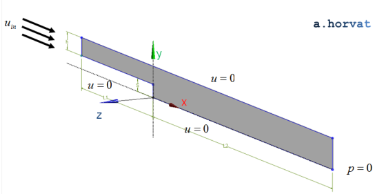
Loading
The inflow velocity profile consistent with the laminar flow regime is set at the inlet:
`u_(\i\n) = 6u_(ave)((y_1)/h)(1-(y_1)/h)` where `y_1 = y-S`
The friction force and its variation along channel walls further develop the flow profile,
and influence its separation and reattachment.
Material properties
The fluid properties that correspond to incompressible and isothermal air shall be used:
`rho` is density of 1.23 kg/m3;
`mu` is dynamic viscosity of 1.79·10-5 Pa s.
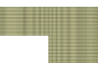
Meshing
In all simulated cases, the numerical grid consists of hexahedral grid elements
elongated in the streamwise direction. Although, a uniform grid spacing of 0.15 mm is used
in the vertical direction, the grid spacing in the horizontal direction expands
from 0.15 mm near the step to 1.5 mm at the inlet, and 0.7 mm at the outlet.
In the z-direction, the 2D grid elements are extruded for a single grid spacing
across the simulation domain.
Section of the hexahedral numerical grid refined near the backward facing step
Initial conditions
Steady-state problem, initial conditions can be arbitrary.
Boundary conditions
Velocity profile at the inlet
`u_(\i\n) = 6u_(ave)((y_1)/h)(1-(y_1)/h)` where `y_1 = y-S`
The average velocity (`u_(ave)`) is derived from the selected values of `Re = rho u_(ave)` `(2h)//mu`.
Reynolds numbers of 389 and 1095 are used for the detailed velocity profile comparison, whereas
the reattachment length is studied for the range of Reynolds numbers between 100 and 350.
The no-slip boundary condition `u = 0.0` `"m"//"s"` is assigned to the bottom and the top wall.
For the outlet boundary, a fixed relative pressure (e.g. `p = 0.0` `"Pa"`) is appropriate. The pressure
absolute value does not influence the flow velocity results.
For the vertical X-Y surfaces, the symmetry or equivalent conditions shall be used.
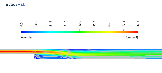
Results
Steady-state simulations were performed using a single precision CFD solver.
Flow velocity streamlines in the channel with the backward facing step at Re=389
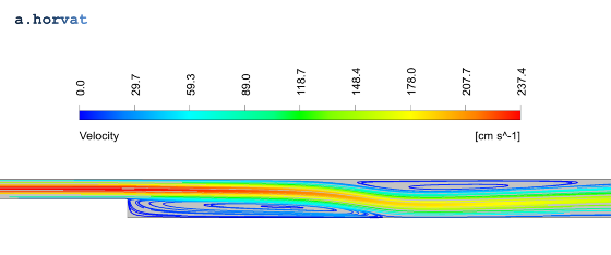
Flow velocity streamlines in the channel with the backward facing step at Re=1095
Velocity vertical profiles are extracted from the CFD simulation results and
compared with the experimental data [1].
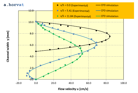
The diagrams below present a comparative analysis of velocity profiles for Reynolds number `(rho u_(ave)` `2h//mu)`
of 389 and 1095, respectively. Only a small subset of the experimental data is presented.
The coordinate `x` represents the downstream distance from the step location normalized with the step height (`S`).
Flow velocity profile comparison for Re = 389 at x/S = 0.0, 5.41 and 11.84
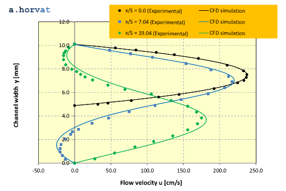
Flow velocity profile comparison for Re = 1095 at x/S = 0.0, 7.04 and 19.04
For validation purposes, quadratic mean (or RMS) of deviation between the experimental data and
the CFD simulation results is calculated for flow velocity at Re = 389:
Location x/S
RMS of deviation
0.0
4.44 m/s
5.41
1.50 m/s
11.84
0.82 m/s
and for Re = 1095:
Location x/S
RMS of deviation
0.0
5.05 m/s
7.04
5.91 m/s
19.04
7.63 m/s
Recorded deviations can be mostly attributed to misalignment of the extracted experimental
data points and the calculated velocity profiles.
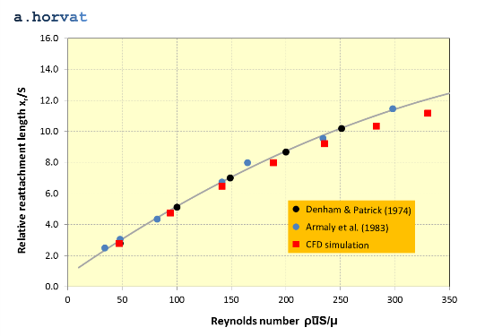
Another important parameter is the flow reattachment, which is characterized by the
change in the flow velocity gradient:
`del_y u < 0 -> del_y u > 0`
The reattachment length, which is the distance from the step to the location of the flow
direction reversal, is calculated and compared to the experimental results [1 & 2].
Reattachment length in the laminar flow regime
Note that the reattachment length (`x_r`) is normalised with the step height (`S`).
It is presented as a function of Reynolds number (`rho u_(ave)` `S//mu`) that is based on the step height (`S`).
Quadratic mean (or RMS) of deviation between the experimental data and the CFD simulation results for
the presented range of Reynolds numbers (`rho u_(ave)` `S//mu`) is 0.68.
B.F. Armaly, F. Durst, J.C.F. Pereira and B. Schoenung, Experimental and theoretical investigation of backward-facing step flow, J. Fluid Mech., 1983, Vol. 127, pp. 473-496.
M.K. Denham and M.A. Patrick, Laminar flow over a downstream-facing step in a two-dimensional flow channel, Trans. Inst. Chem. Engrs, 1974, Vol. 52, p. 361.
Dr Andrei Horvat
M.Sc. Mechanical Eng.
Ph.D. Nuclear Eng.